The last Project Why Wait update marked the first time the cab made an appearance since 2016. If you were excited for more metal work I’m sorry. It’s coming, but for this post the cab is back in the corner while I button up a bit more of the chassis.
The chassis is currently on the cusp of being a proper roller. Seeing it lay running board once more would be super motivating, but before that happens there’s a few things I need to strike off the list first.
One of those ‘to do’ items was installing the Air Lift Performance 3H ride height sensors.
If you remember from the un-boxing post I went with 3H Managment so neither my wife or I have to worry about the truck riding too low, or more importantly too high, at any given time.
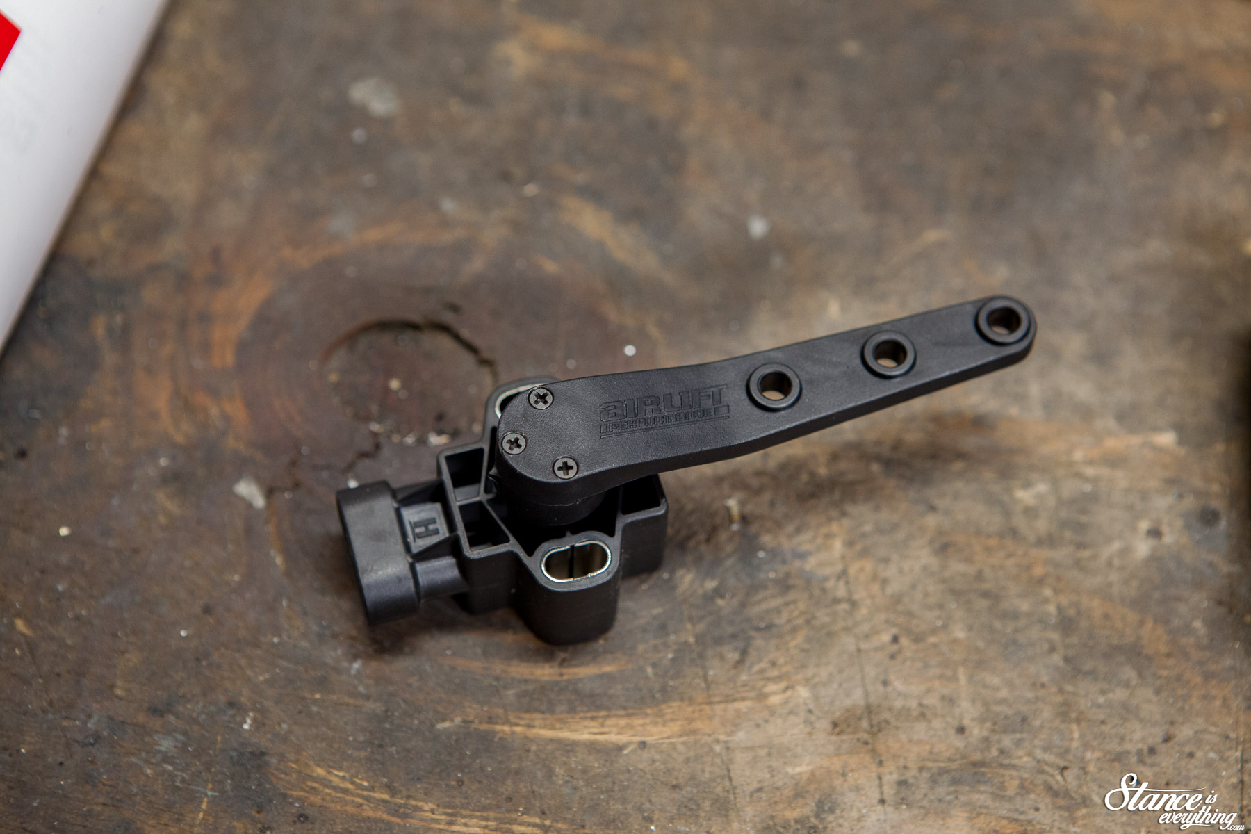
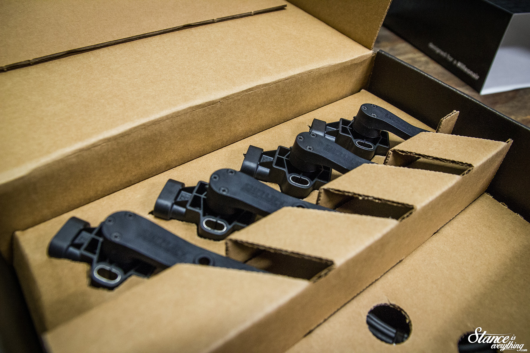 To be able to accurately monitor ride height, once different loads are introduced, the 3H system requires the installation of the ride height sensors pictured above.
Depending on who you ask height sensors are either fairly easy to install, or quite complex.
We’ve all heard the “hard to install” height sensor schpeal of companies who’ve opted not to release a sensor based system.
Aware of the existing stigma Air Lift Performance produced an excellent set of instructions to accompany their kit. As someone who spent years assembling model cars, I really appreciate a good set of numbered directions.
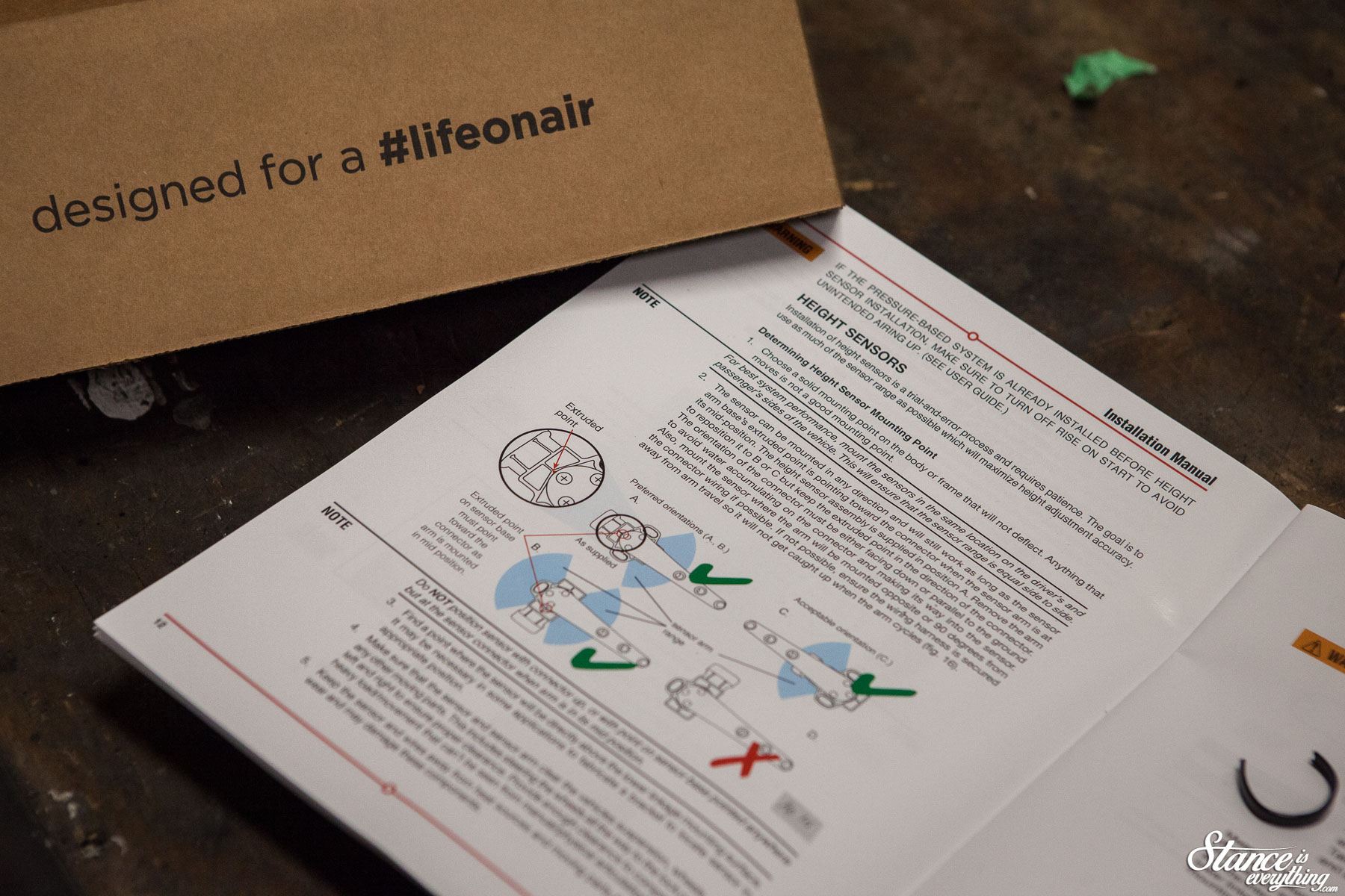
That said, Air Lift Performance does warn installing the sensors is a time-consuming process. Luckily with this truck I have all the time in the world.
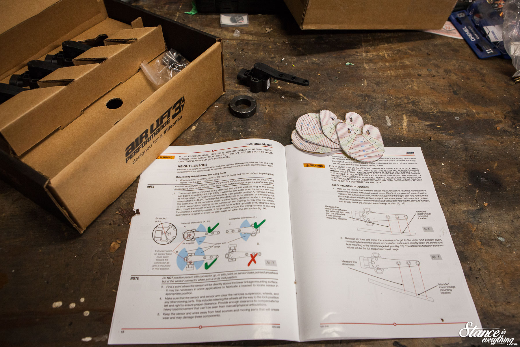
Looking back at my installation experience, one of the best things Air Lift included in the documentation were the sensor range templates. These are used to make sure the sensors articulation is within operating limits when no power is run to the system.
I used these extensively during my install.
Quick tip: you can make them a lot more durable by affixing them to thin cardboard. Cereal boxes work a treat.
I chose to start the job at the front of the truck. I reasoned this would be where most of the complications would lie.
It didn’t take long to find challenge #1. Because Project Why Wait runs Allstar performance tubular upper control arms, there wasn’t a great spot to mount the sensor linkage.
I could have tapped, or welded to the control arm, but I really didn’t feel comfortable with either option.
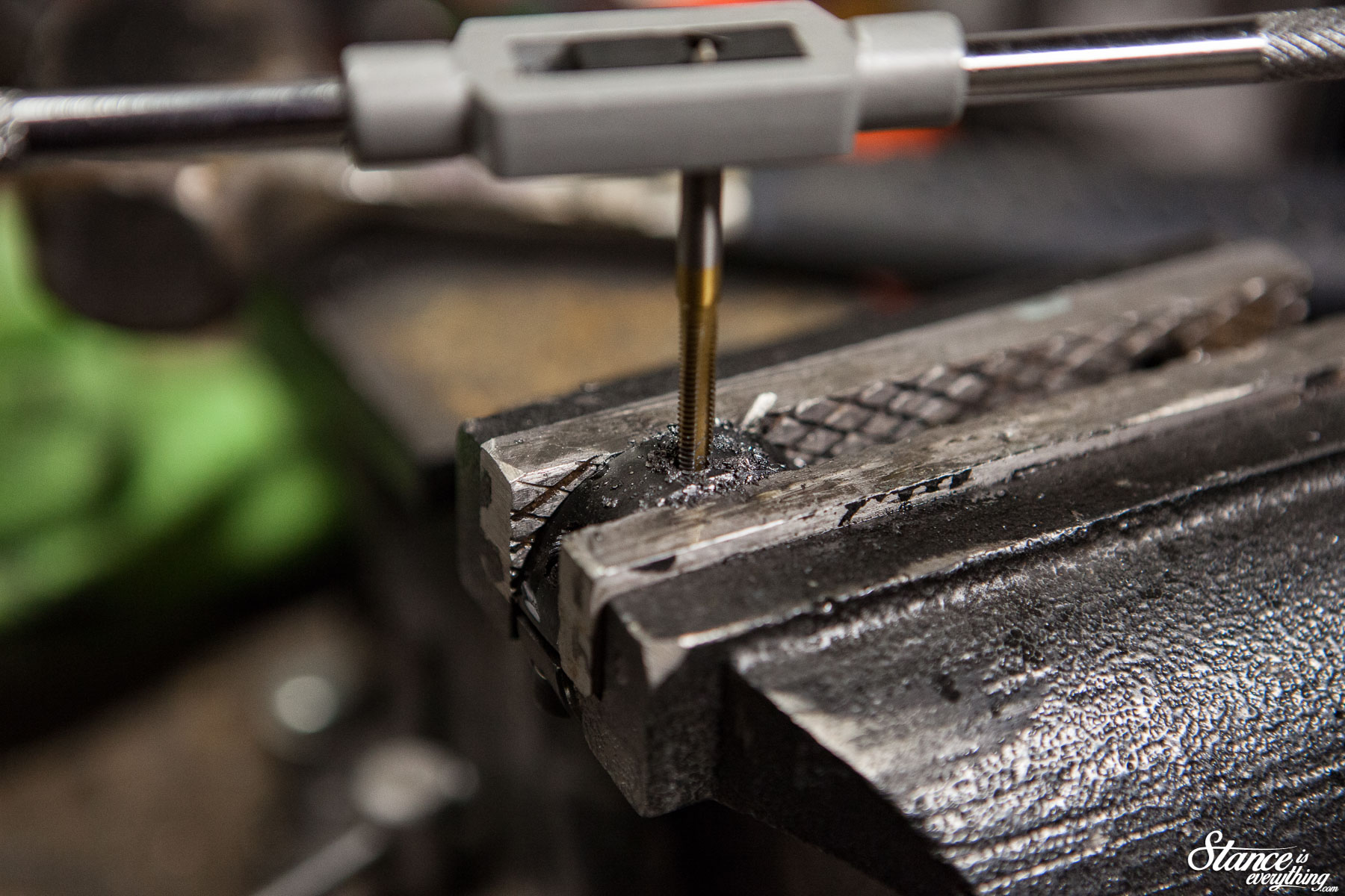
 The solution for this problem came by way of Amazon, where I grabbed a pair of 1″ spit collars. Drilled and tapped these solved my problem perfectly.
Additionally not being permanently fixed, this mounting point allows for further adjustment down the road. I paid about $20 shipped for the collars, though it took me awhile to find a vendor that would ship to Canada.
Truth be told I think my set was used, but no big deal in the end.

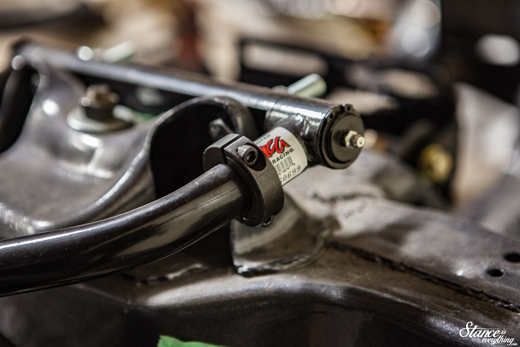
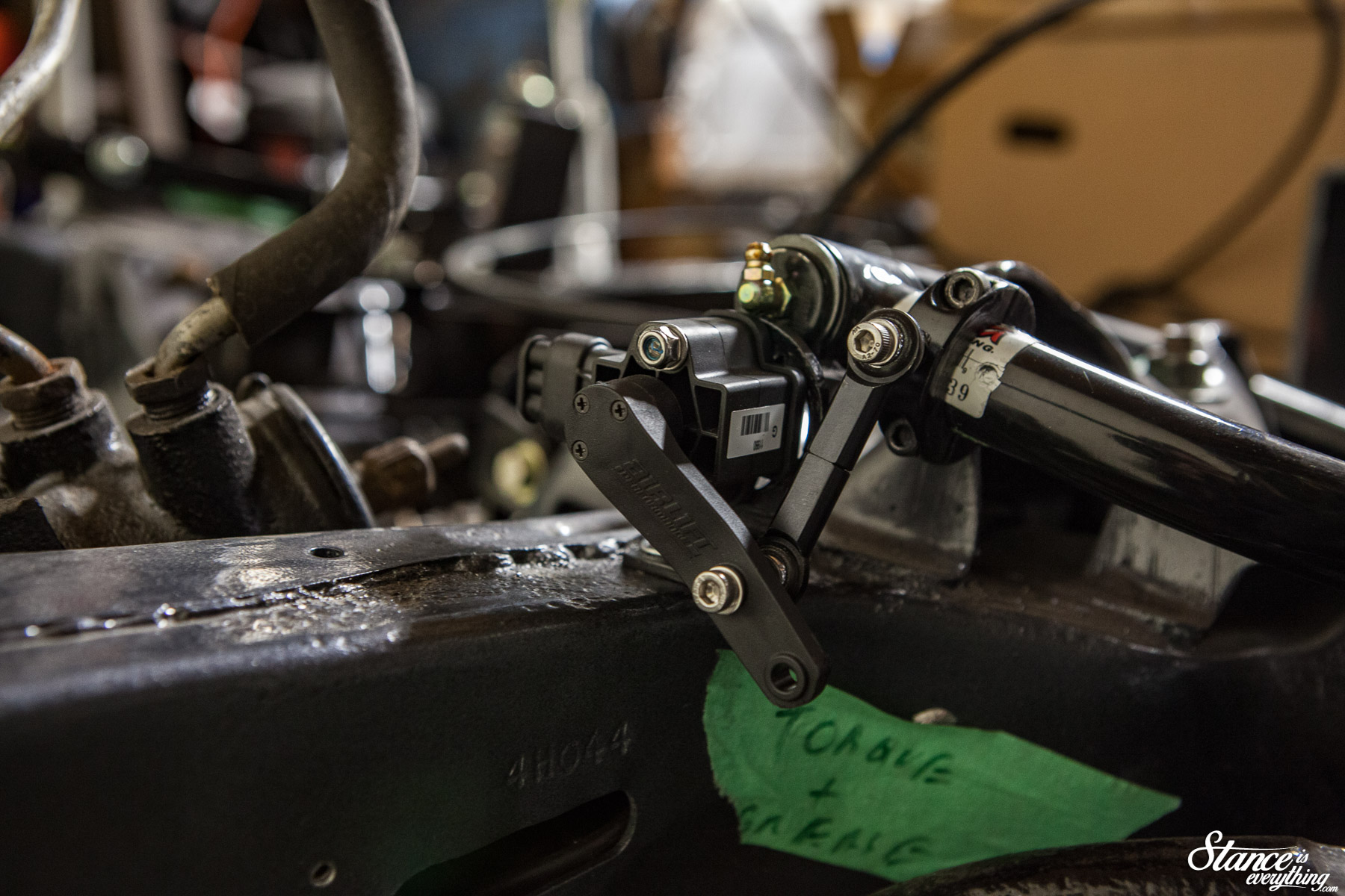
Next came mounting the sensor itself. Usually the sensor is mounted above the suspension mounting point. In my instance doing so would be a little complicated so I called Air Lift’s support to see if it could be avoided. They confirmed that it while the manual prescribes one way, it will work the other.
The configuration you see above was take one. It worked mechanically, but ultimately it had a pretty big flaw.
I can be a little slow at times so, it took mounting the sensors completely before I put a wheel on and realized things were no bueno.
Had I left the sensor where it was, the first time I turned it would have been history.
Looking back I’m not 100% sure what I was thinking the night I thought that spot was a good idea. I must have under estimated how close the wheel gets to the frame when steering lock-to-lock.
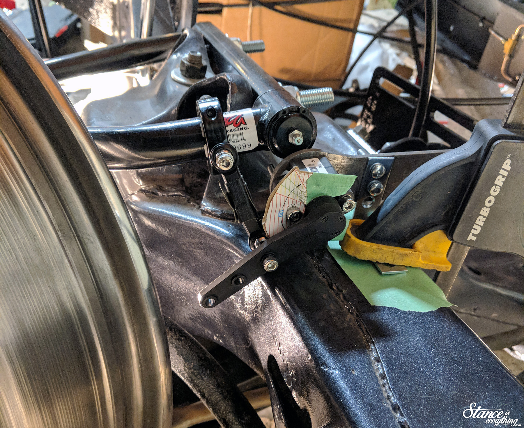
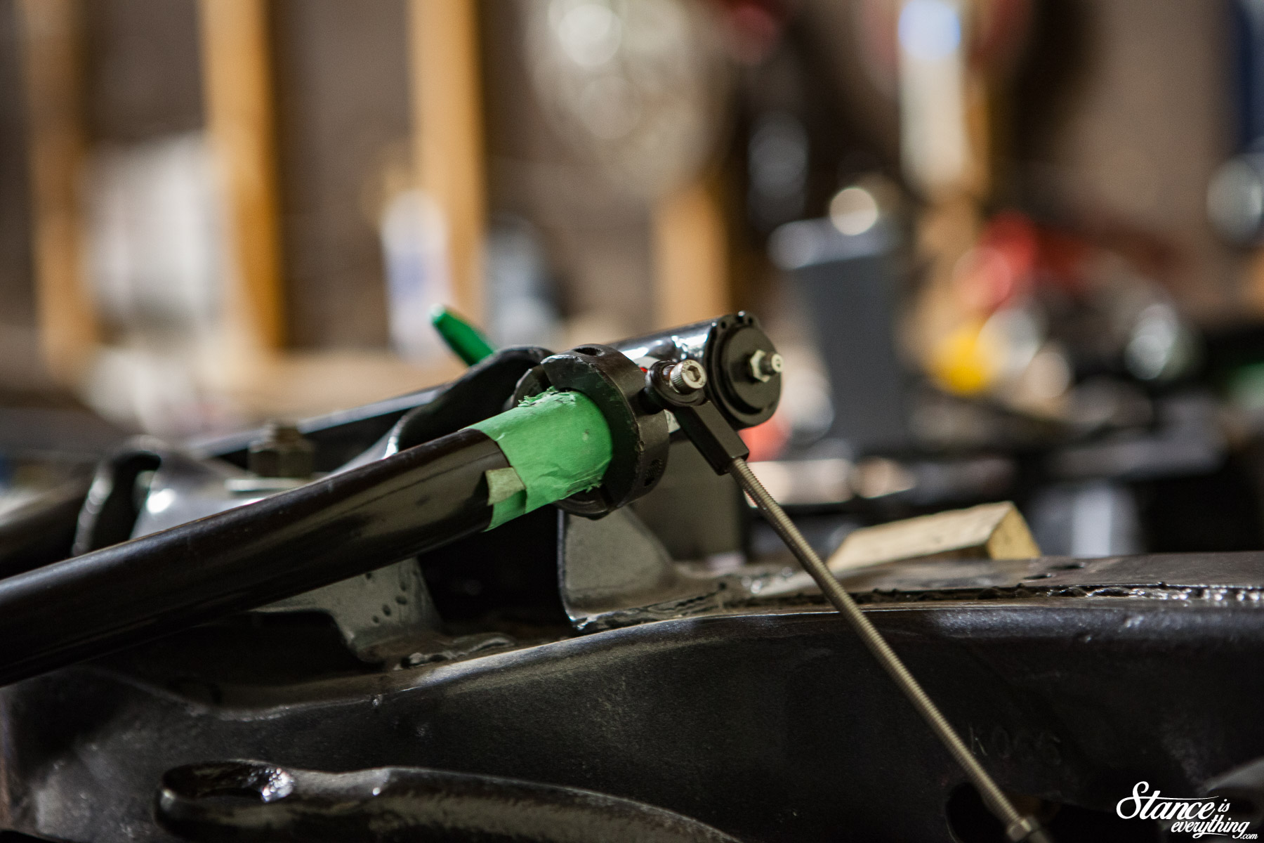
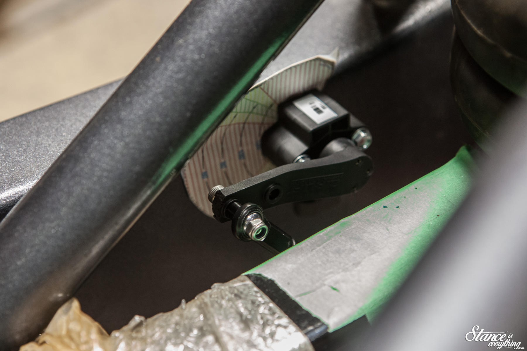
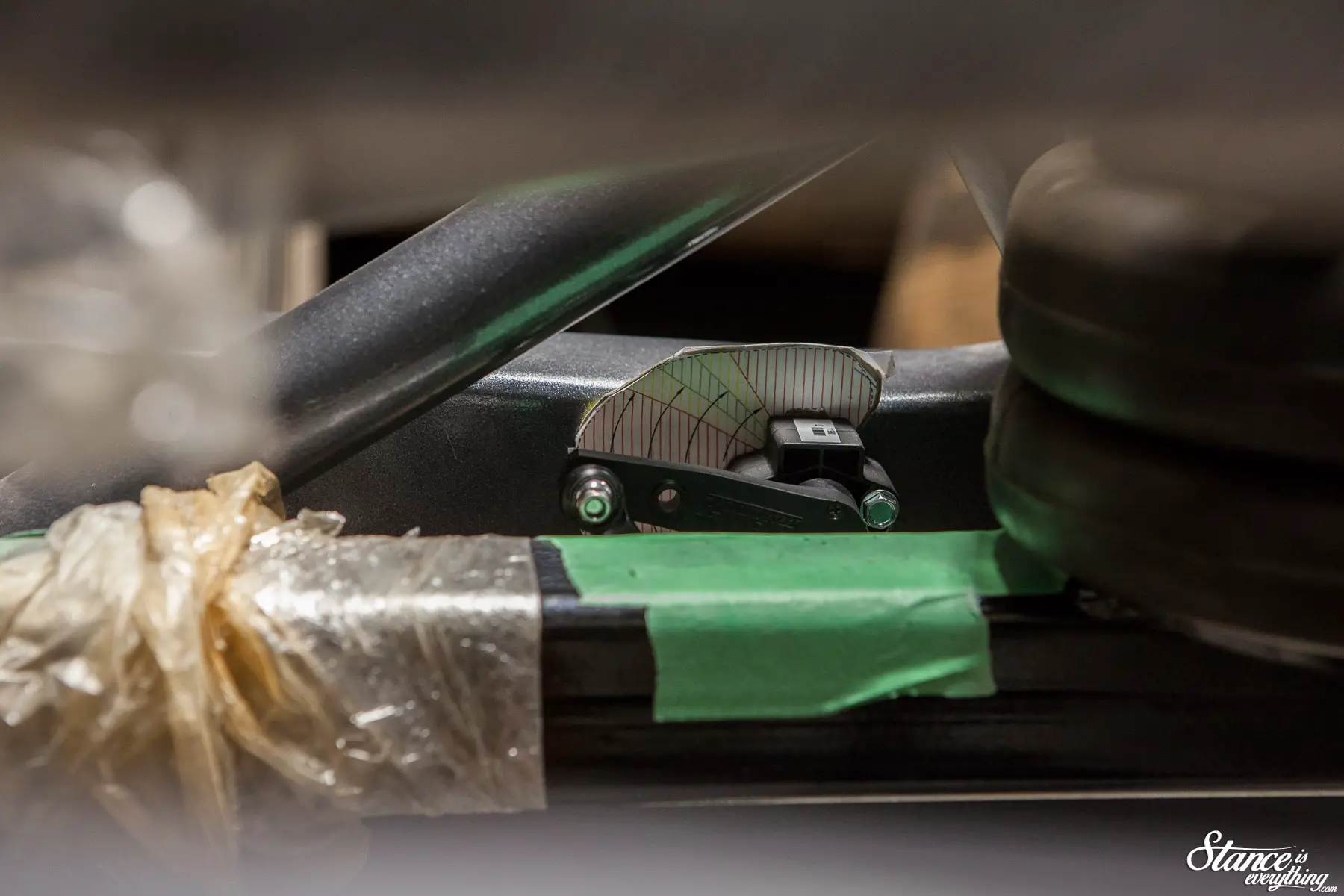
Using a sensor mounting bracket I got from Air Assisted (thanks Kevin!) I was able to find an alternate position on top of the frame rail. I kept everything as tight to the control arm as possible to lower the chance it would interfere with any other components.
Above was a range test, hence the duct tape holding the two rod ends together, and the quick clamp mounting solution with random home hardware.
 Once I was satisfied that position two would work, I set out shortening and re clocking the sensor arm.
This falls within Air Lift’s permissible system modifications and they cover how to do it throuougly in the instructions.
In a nutshell there’s an extruded point on the arm that you have to make sure is oriented correctly. As long as that is correct you can pretty well do whatever you like.
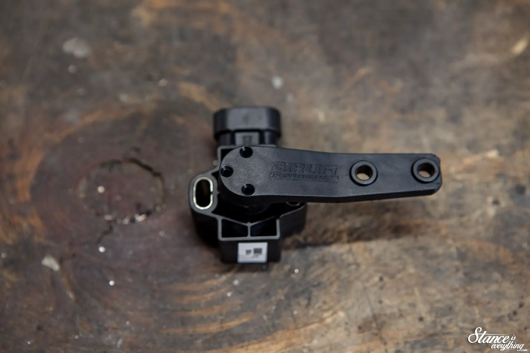
A bit of paint on the collar, and sensor mounting bracket, and you end up with the set up below. It’s worth noting that I cut down the threaded rod that connects the two rod ends significantly to make this work.
That is another permissible modification illustrated in the 3H instructions.
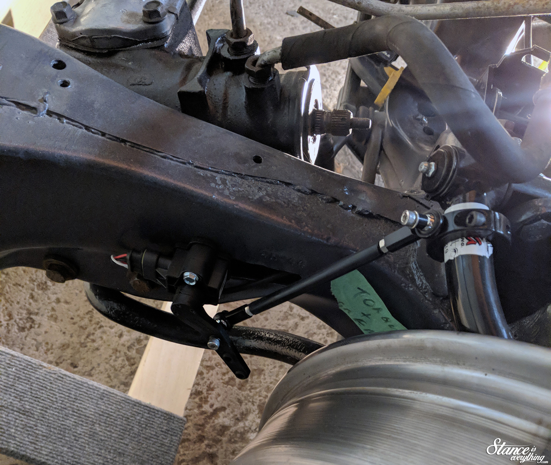
After doing the front twice, the rear was fairly straight forward. Not having to account for steering and having two flat surfaces to mount to really helps speed things along.
I mounted the sensor to the frame rail, and used the lower link bar as my suspension point.
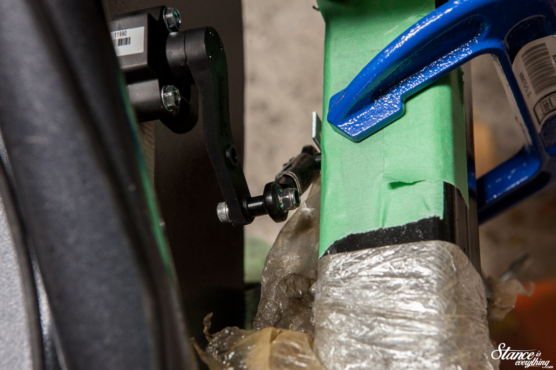
Mounting to the lower link bar was acheived with a simple right angle bracket purchased from Home Depot.
Much like the front, I clamped everything in position before running the suspension through it’s full up and down range.
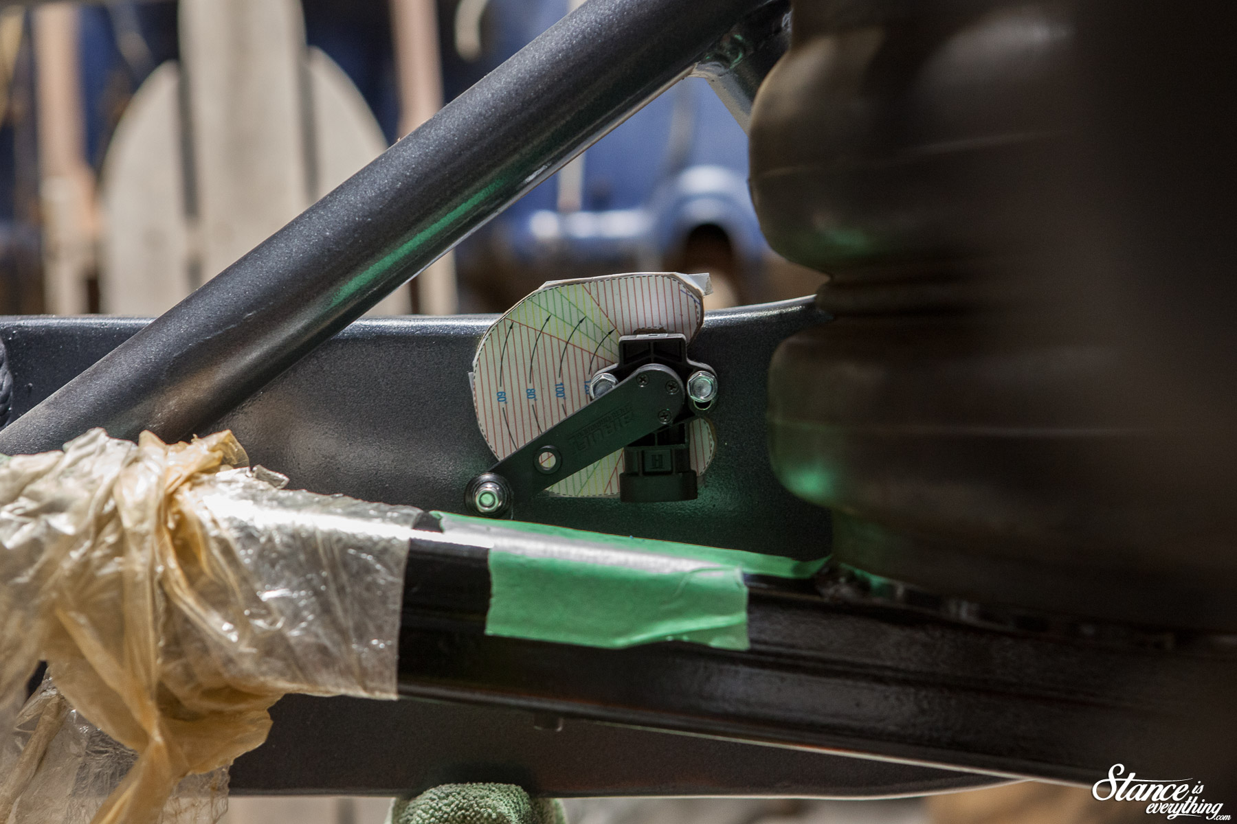
With no bind present, and everything falling inside of the red, I again trimmed the sensor arm.
 I also slotted the mount on the lower link bar ever so slightly. Again this was done to allow for further finagling down the line.
The final trick to calling this job done was running the wiring for both the sensors and managment ecu/manifold combination.
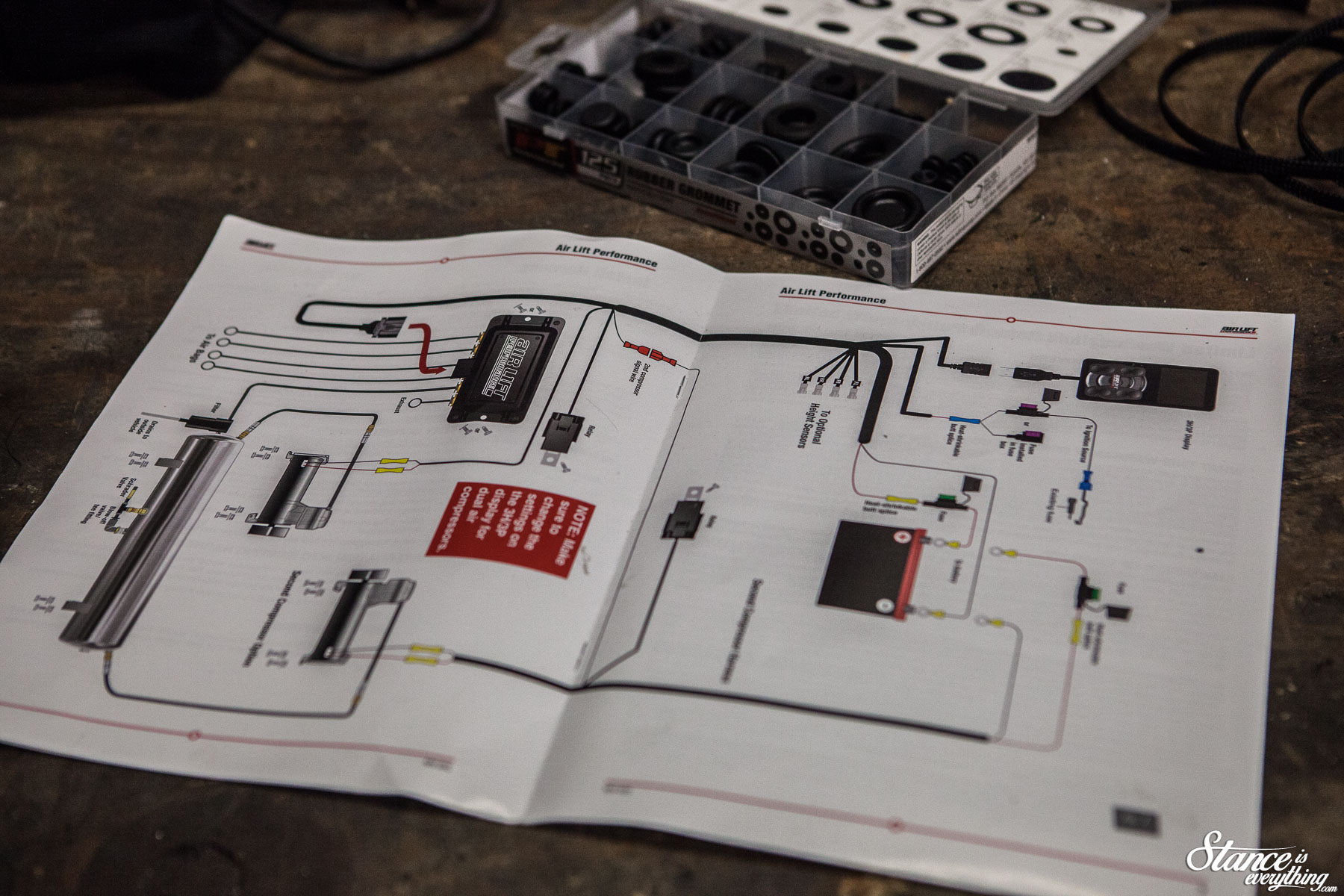
Though the illustration above might make it look a little involved the wiring really is straight forward.
The controller connection cord (USB), trigger wire, and power and negative go to the front of the vehicle. A relay, and the main plug for the harness remain in the rear.
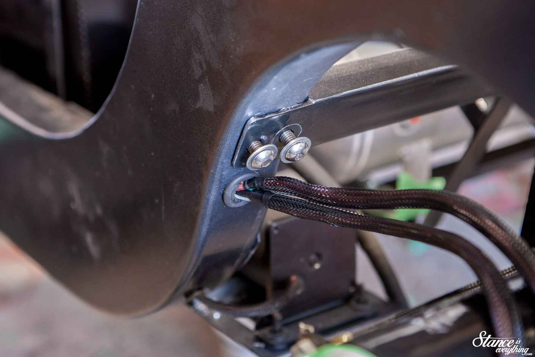
I’m sure there were a few quicker ways I could have gone about running the wiring the entire system but the cleanest way was through the frame.
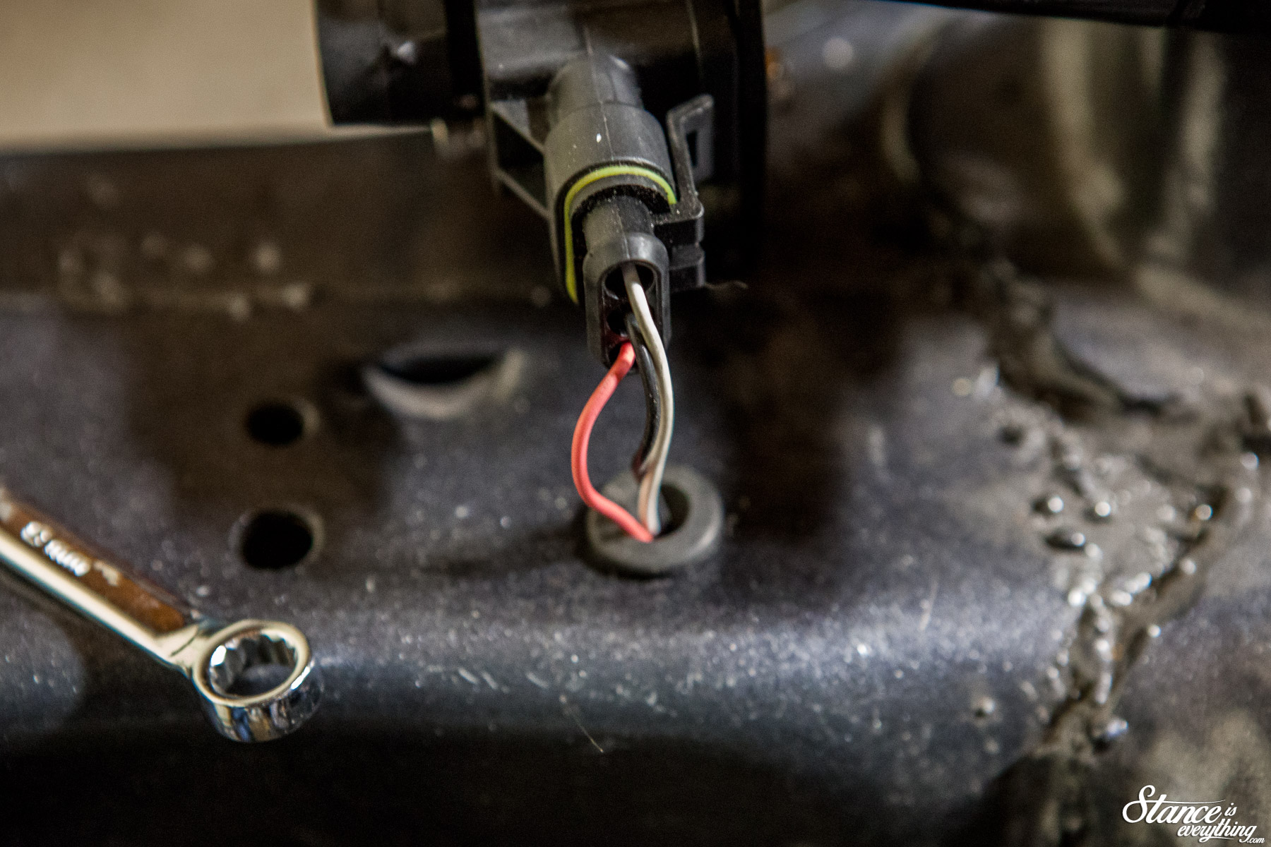
Up front the driver’s side sensor enters the frame almost immediatly, crosses over to the passenger side via the engine crossmember, and joins the passenger side sensor on its trip to the rear.
At this point it goes through the rear crossmember, where a power and negative wire are going the opposite direction up to the battery, as part of the second compressor harness.
The rear sensors are done very similarily to the front, though they start behind rear cross member.
Everything is loomed and grommeted to ensure that it works for years to come. Running these wires isn’t exactly something I want to do on any sort of regular basis.
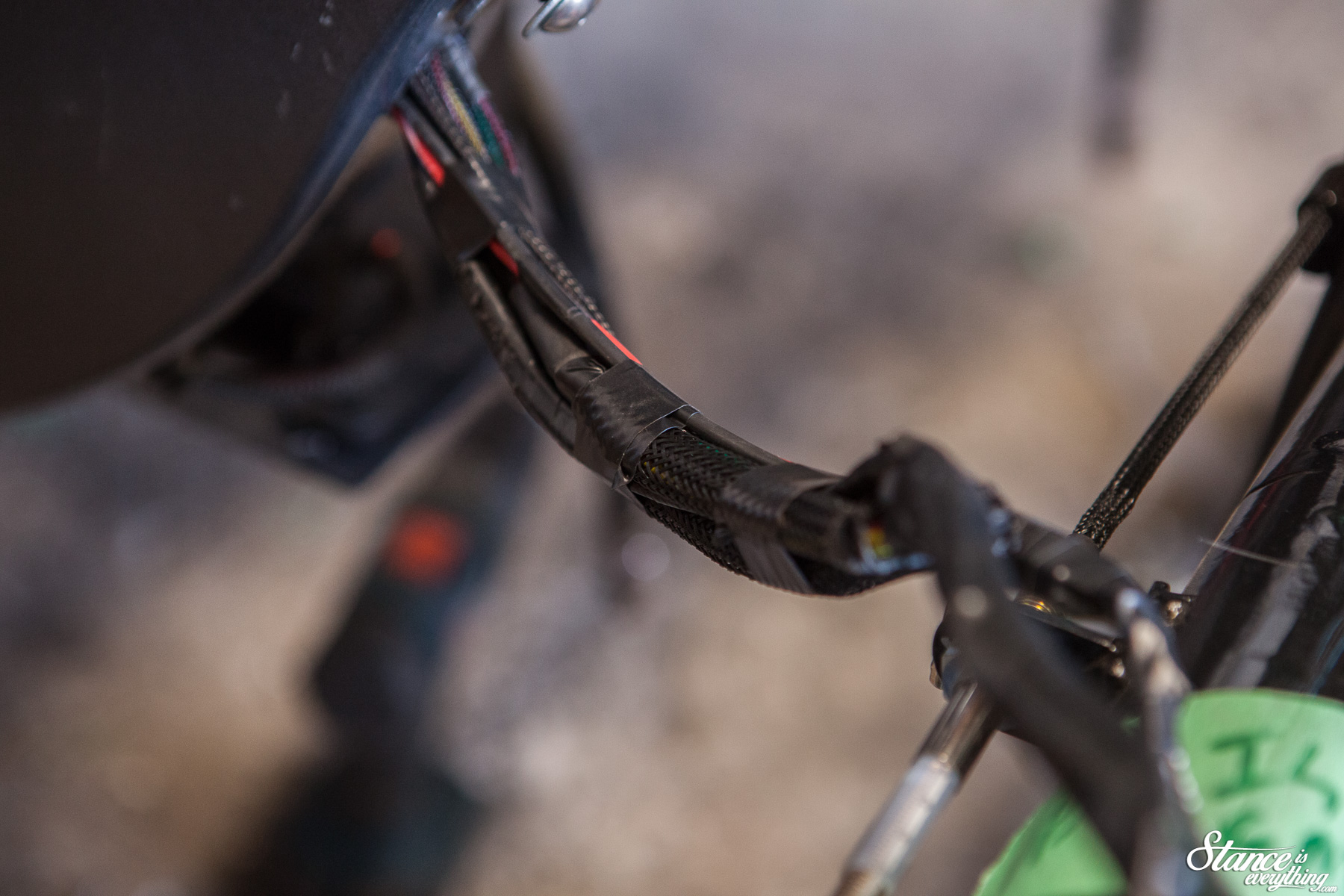
With all of the connections made I wrapped the harness tightly in electrical tape before snaking it back through the frame.
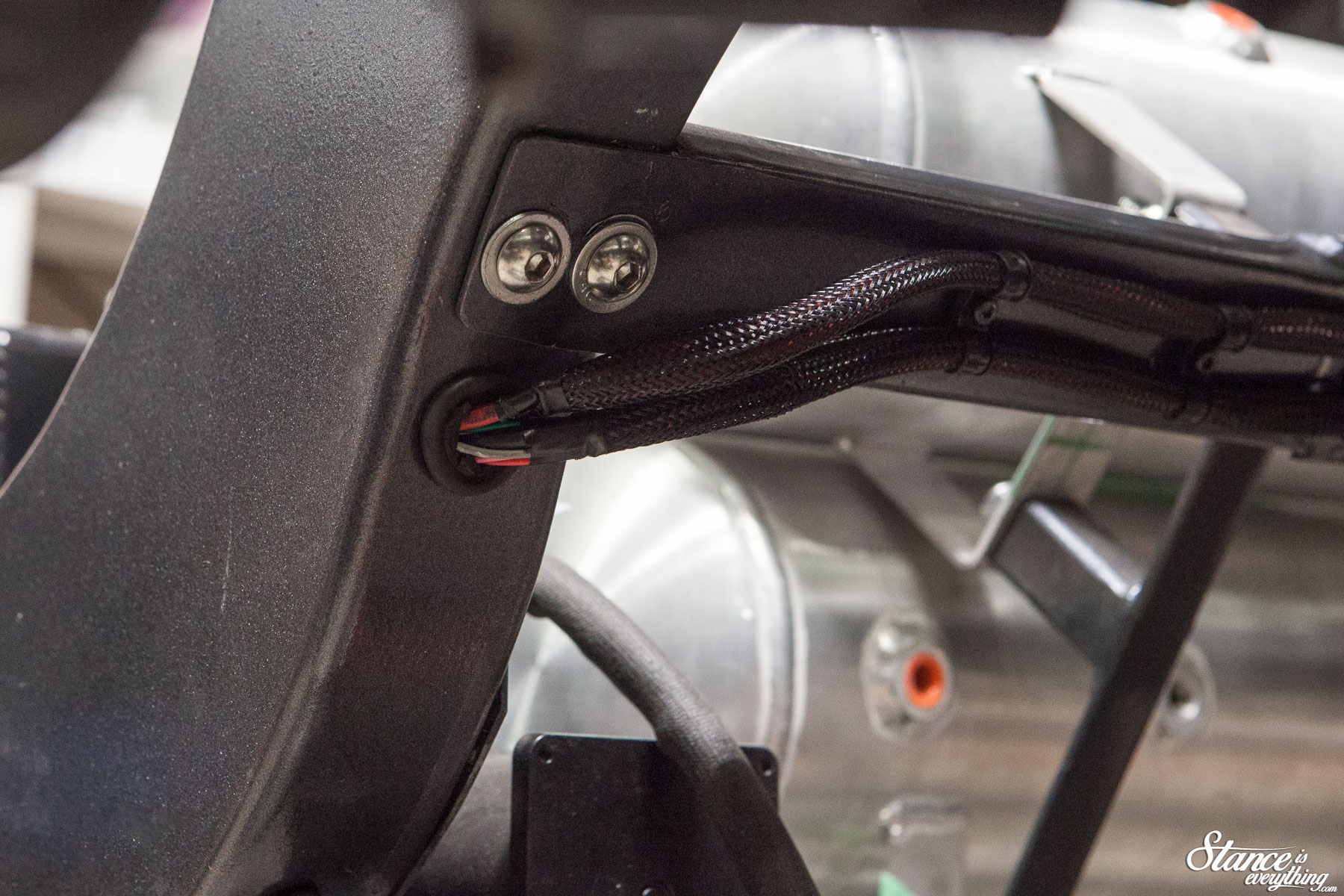
I also at this point drilled holes from the compressor wiring that also runs through the frame.
The main harness was fed through the frame up to the point where the relay and main plug branch off from each other.
Theoretically I could have modified the harness so this junction was closer to where I was going to be terminating my connections. But, this would have voided my warranty and added another ten or so points on failure.
In comparison living with the extra wiring is much easier.
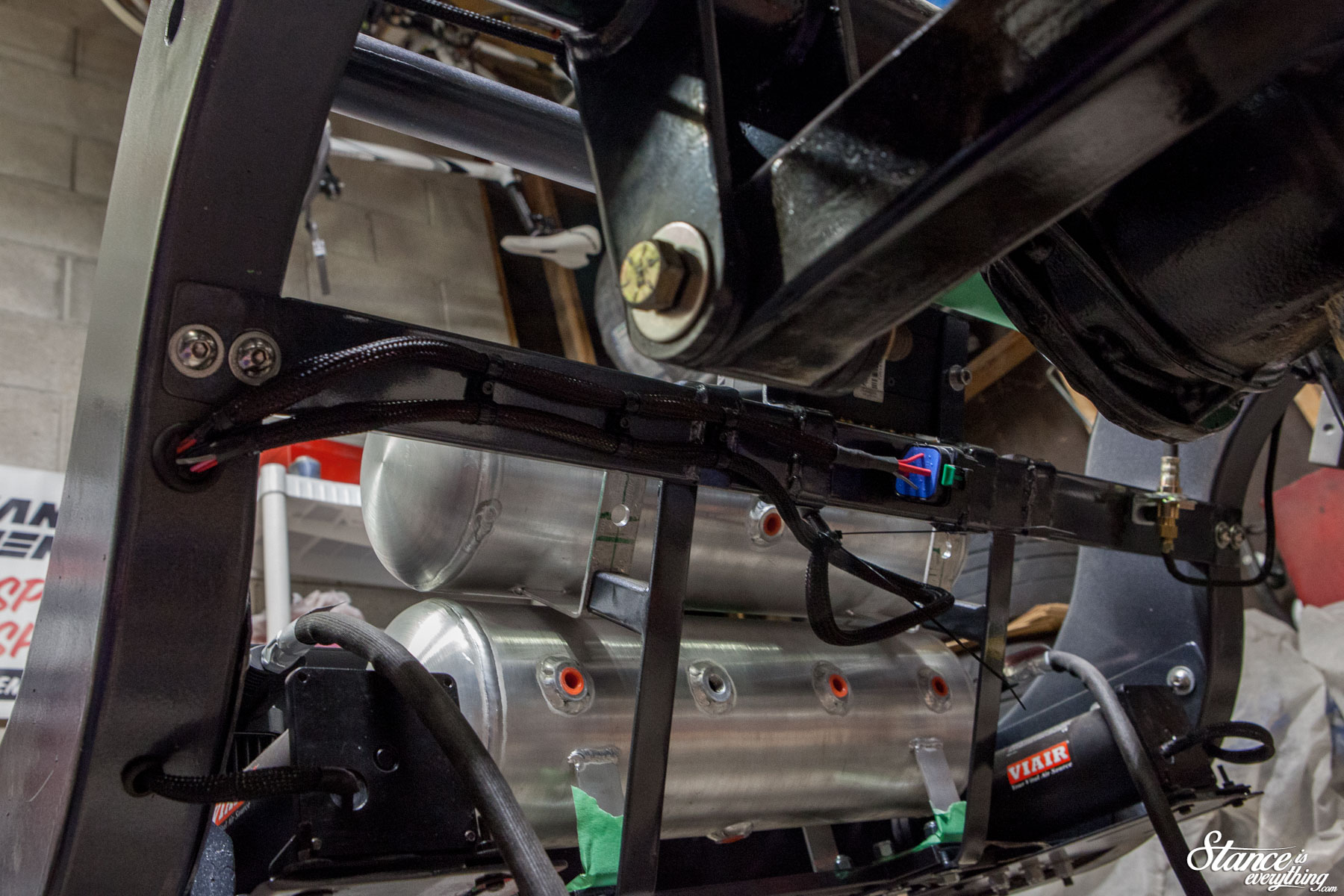
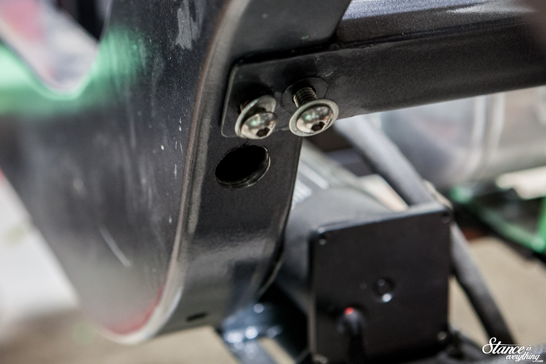
Viewed from under neath the truck this is what all of the wiring looks like. There’s an extra loop of wiring in the middle there for the main sensor plug.
I could call it a service loop, but really I’m not 100% sure the tidiest way to deal with it.
That being said it isn’t really viewable from the angle below which is where most people will be looking at the back half.
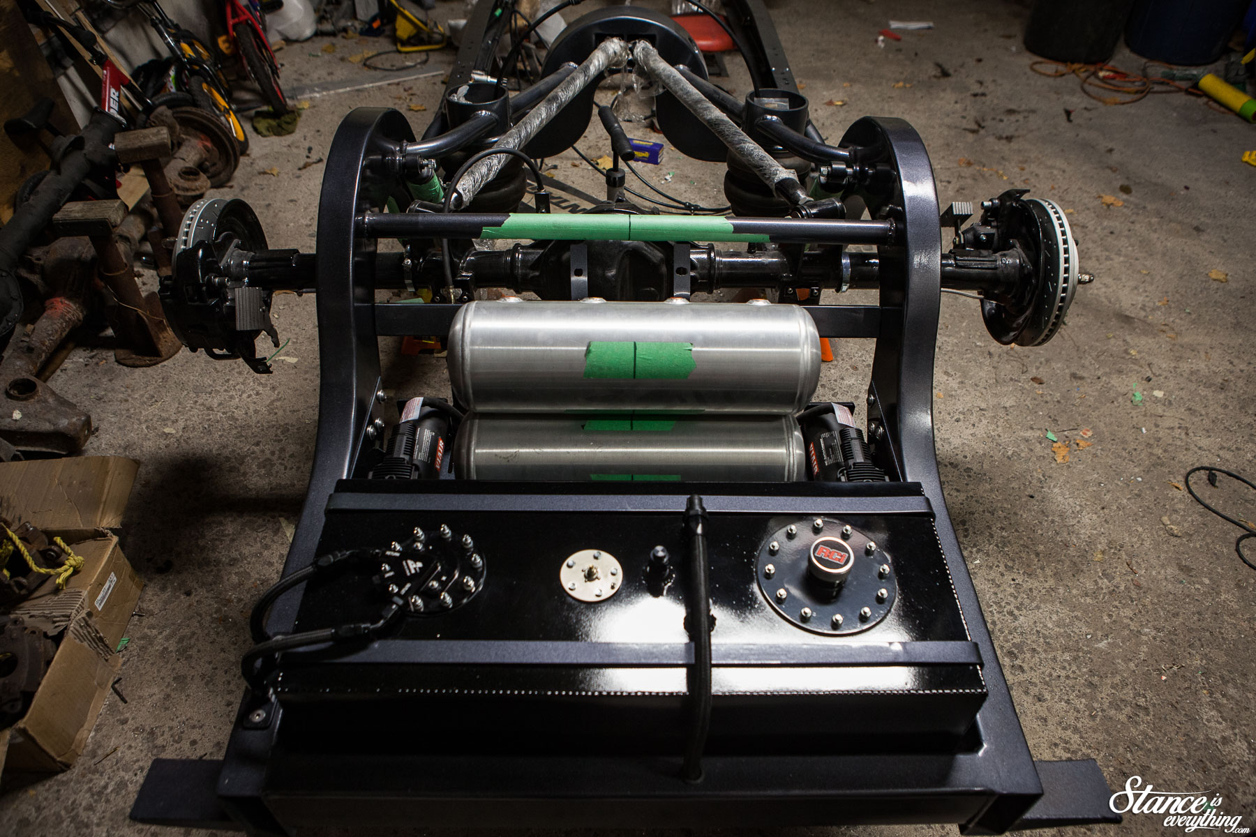
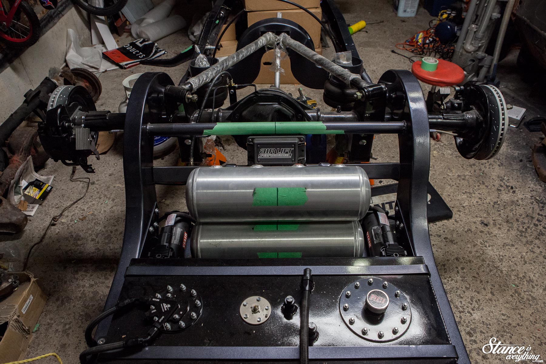
While the photos above look nearly identical, the bottom has the management mounted, and wired, and brake lines run. Neither of which can really be seen which is exactly what I wanted.
Next up, probably few months of metal work on the cab before the motor comes back.
It’s finally double digits in the garage now so I am super motivated to tear through as much as possible. You can follow the updates between the updates on Instagram but there’s more to come here on the site as well.
Stay tuned.


I absolutely love following your progress. This things going to be fantastic! Thank you so much for documenting everything your doing so well and sharing it with us!
Good man! Nice attention to detail!
I really love following your progress. This thing going to be fantastic! Thank you so much for documenting everything you’re doing so well and sharing it with us!
You have a great progress “style” you explain everything even the tasks you have not done in the post, keep it up